Just Learning I2C
Telecom I2C Controller for Power Supplies
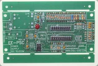
The EE-PSC controls most high end power supplies by just hooking up control signals from the power supply to the unit. This allows your power supply to be monitored / controlled remotely by a digital data I2C bus host controller, from a remote location. Testing, temperature, voltages, signals and alarm set-points or resetting the power supply. No need to do a field visit to see if the power supply is working. The EE-PSC can be configured for different addresses from just one I2C data bus. You can program a serial number into the each unit. There is no guess work. The EE-PSC follows all standard I2C commands and protocol. You can use external 5 volts supplied from another power supply to power the module. Monitor voltage range is 3.3– 48 +/- volts primary output. AUX monitor voltage + 5 Vdc. There are 7 TTL I/O signal lines that can be use for any type of TTL communications.
PCF8574AT (I2C serial to parallel I/O)
PDF-File
M24C01 (I2C EEPROMs) PDF-FILE
LM75CIMT-5 (I2C temperature sensor) PDF-File
LM80CIMT-5 (I2C power supply + fan control +voltage
and trip measurements + tempeature) PDF-File
Electronic PDF Schematic block diagram for EEPSC telecom PCB
-
Features Include:
-
Power Supply Inhibit: TTL signal, sink or source
-
Power Supply Aux: TTL signal (5 volt analog)
-
AC Power Good : TTL signal, sink or source
-
DC Power Good : TTL signal, sink or source
-
Fault Signal: TTL signal, sink or source
-
Margin Signal 1: TTL signal, sink or source
-
Margin Signal 2: TTL signal, sink or source
-
Selectable pull-up resistors TTL (5Vdc 10K for open collector IC's)
-
Fan Tack Fault 1: Analog Input / read back (frequency/pulse rate)
-
Fan Tack Fault 2: Analog Input / read back (frequency/pulse rate)
-
Selectable Dividers Resistors (V1 Analog Input) 3.3-48.0 Vdc
-
Voltage input (V3) / read back 0-2 Vdc extended range with dividers resistors ( optional)
-
Primary Voltage Output (source): Voltage input / read back (V1)
-
Aux Voltage Output (source): Voltage input / read back (5.0 Vdc V2)
-
Alarm Set Point Upper: (V1) (V2) (V3) (Fan Tack 1&2) (Air Temperature Monitor) (V4 if used)
-
Alarm Set Point Lower: (V1) (V2) (V3) (Fan Tack 1&2) (Air Temperature Monitor) (V4 if used)
-
Air Temperature Monitor (-25 to 100C)
-
EEprom (256 x 8) serial number (random or serial I/O)
-
I2C communications slave mode only (standard 5Vdc signal type, speed 1-100Khz )
-
Selectable addressing of module, seven address locations / module ( 000-111 ) this is connector programmable
-
7 Module Control / I2C Bus Connection (seven module on one I2C host bus)
-
External DC Power 5Vdc (Isolation Required)
-
Operation Temperature Range -25C to + 85C
-
Connectors for signal hook-up (2x20 pin stake type pins)
-
High Noise Immunity
-
Sink Current TTL (10 ma) Maximum all TTL
-
Source Current TTL (0. 5 ma) standard /optional 10ma max.
-
Optional / Over Temperature Alarm (analog signal alarm )
-
Size: W 2.1 x L 4.5 x H 1.75
-
Mounting Holes: 4 x #6 screws
-
ICs: PCF8574AT / M24C01 / LM75CIMT-5 / LM80CIMT-5 /
-
Learn I2C communication by building what you need from a bare board.
( Populated Board / Schematics / Parts List / Layout comes as shown )
Solder on the IC's you need to test and program.
Good for I2C PCF8574AT(serial to parallel I/O) / M24C01(most I2C EEPROMs) /I2C LM75CIMT-5 (temperature sensor) / I2C LM80CIMT-5 (power supply + fan control +voltage and trip measurements + tempeature) Runs on 5 Volts DC
Comes as shown Schematic + Layout - No IC's (Populated Board)
Great for learning I2C
Homepage: Http://\www.Exec-Eng.com/